Hi Mike,
Yes, you have it right. The valve body had a replaceable seat ring which was made of bronze, while the valve plug had a replaceable seat ring originally made with glass-filled Teflon.
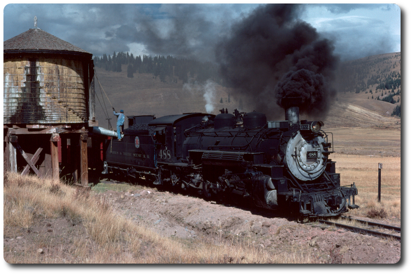
We had been having such good success using Teflon in smaller applications such as the try-cocks and fountain valves that I decided to try it on the main throttle. Unfortunately, or, perhaps, predictably, the Teflon ring broke up during the first trip (so I was told, as I wasn't there), and pieces of it were found in the cylinder cocks. The problem was that at 388 degrees F, the saturated steam temperature at 200 psi, the Teflon was very close to its upper working temperature limit. That, coupled with the relatively small section of the seat ring compared to its diameter of near 9 inches, plus the effect of wet steam rushing over the ring at high velocity, led to the failure. I had warned Steve (Jackson), the shop foreman, and George Connor, head of the operating department, that the use of Teflon in the throttle was experimental and to advise the enginemen to be alert to possible problems. The throttle design was such that with the Teflon seat ring completely gone, the valve plug would sit down on the body and give a safe, if not leak-tight, shutoff of the throttle. The engine crew didn't mention any problems in handling the locomotive as a result of the disintegrated Teflon ring.
The fix was a fairly simple matter of machining a replacement ring out of bronze, which, I believe was done by Arnold Blagg. At that time, I believe they also modified the seat angle from 60 degrees to 70 degrees to give a more graduated control of steam flow.
One of my memmories of you helping me on that project was when I was showing you how to tap the holes in the valve body for the seat ring retainer. I think there were eight 1/4-20 blind bolt holes on about a 9-1/2" bolt circle. We set the body up on the Series II Bridgeport, and after drilling the first hole to the required depth with the correct tap drill, I put the 1/4-20 tap directly into the spindle chuck, brought the spindle down to where the tap was just above the hole, then turned the spindle motor on and right back off, then hand-fed the spindle down as the tap entered the hole. The idea was that the resistance of the tap as it began cutting was supposed to cause the spindle to coast to a stop after a few turns. Then the chuck could be released from the tap and moved up out of the way, leaving the tap started perfectly straight into the hole, to be finished tapping to the bottom by hand. The procedure works great in a belt drive drill press or in the standard size Bridgeport, but what I wasn't counting on was the increased size and momentum of the larger Series II spindle. The result was that we both watched the spindle keep turning and turning, almost in slow motion, till the tap reached the bottom of the hole and promptly snapped off. A great lesson in how not to tap a shallow blind hole with a Series II Bridgeport.


