Tie Spacing
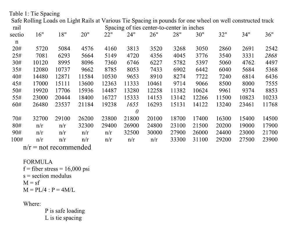
In early 2009, the Yahoo Park Trains group had a discussion on what rail loading was for different tie spacing. The basic offering was a table which I have retyped below (Table 1). The original PDF was so many copies removed that it would not have been legible.
Table 1

In back channel discussions with Terry Miller, several questions were asked and the results are presented here.
The first item to understand has to do with what is called “significant digits”. Significant digits is loosely related to tolerances. Tolerances are a continuing topic in this series. In CEv1 (Civil Engineering for Outdoor Railroads Volume 1), tolerance it discussed with respect to degree of curvature in the chapter Curvature and Superelevation (page 4) where I prove that the error between the chord and the arc definitions of degree of curvature differ by less than 1% until a radius of 200 feet is achieved.
The concepts of error and acceptable error were discussed with respect to level lines and elevations in the CEv1 on page 34. The level line is not a straight line but circular arch that is based on the local direction of gravity. Depending on the accuracy you accept, the level line can be considered a straight line.
Terry located formulas for a simply supported beams. These are covered in Chapter 7 - Loading Diagrams of “Civil Engineering for Outdoor Railroads Volume 2 - Bridges”. The loading diagram in Figure 7.2 is the one that describes the rail loading and tie spacing situation very well. (Figure ??.1)
One of the items in the formula is deflection. A search on the web will not yield what an acceptable deflection is. This is due to the fact that every application has a different acceptable deflection. As discussed in in Chapter 4 - Failure Modes of “Civil Engineering for Outdoor Railroads Volume 2 - Bridges”, a collapse of a bridge is a failure. A failure can also be defined as any deflection where the rider feels uncomfortable with the allowed deflection.
In two paragraphs from Volume 2, the issue of deflection is described in a nut shell.
“When I built my test track in the back yard, I used 2"x2" pine stringers on one trestle that were 4 feet long between bents. Although no where near collapsing, several people said they were uncomfortable with the 3/16" deflection - they said it felt like it was going to collapse.
As an aside, have you ever noticed that some flatbed tractor trailers have a hump in the middle when they are unloaded? The goal of these trailers is to keep weight down. So they design the bed to deform to a straight line when loaded with the maximum allowable load. Again this points out that deflection is not always a failure. It depends on how you define failure.”
What this points out is that deflection failures can be defined in many ways. The definition of an acceptable deflection is more of an art than a science.
If you want to define a deflection, start with a number such as 0.5% of the unsupported span. For a distance of 24" tie spacing, it would yield an allowable deflection of about 1/4". If this turns out too much for you, feel free to reduce it to 0.125” or 0.1”.
If you want to see what these deflections would look like, put two (2) nails in a 2x4 at your center-to-center tie spacing. Put a nail at the midpoint add a block of scrape wood to the side of middle nail. Take a piece of metal (longer than the tie spacing) of a flexible metal (like that used on HO scale rulers or a piece of sheet metal) and place it so it contacts the two end nails and the deflection block at the middle nail.
This actually does not show the true deflection - the true deflection is less. This is because the formula you are using is a simply supported beam. What you have for a rail is actuality a continuous beam at the supports that would resist deflection even more.
Returning to the tie spacing issue, are the results and equations in Table 1 correct? After using information from L. B. Foster and working out the equations, my results determined that the equations and the tabular results are basically correct.
On the L. B. Foster web site, there are two section moduli (S) listed. The head section modulus and the base section modulus. First thing I had to figure out was the section modulus. 60# rail [and greater] has two section moduli: 1) Sh for the head and 2) Sb for the base. Table 1 results are based on SA rail and uses Sh.
The "f = fiber stress = 16,000 psi" comes from the strength of steel. The strength of steel is based on the type of steel used. Steel comes in many strengths - 36 ksi is one of the more common steels used. Other strengths include 30 ksi, and 60 ksi (ksi = 1,000 psi). Normally, the Fy (yield strength) is based on the maximum end of the elastic region of the stress-strain curve. For calculations, the Fy = 30 ksi is reduced to Fv = 29 ksi (about 80% of Fy). According to AISC (American Institute of Steel Construction), the Fv should be reduced to somewhere between 66% and 50% depending on a lot of different support conditions. This is F. According to the AASHO (American Association of State Highway Officials) the factor used is 0.55. For 36 ksi steel, this becomes 29,000 * .55 psi or 15,950 psi which is about the 16,000 psi in the chart.
After determining this, I was able to verify 60#, 40#, 30#, 25# and 20# rail to within 0.5% with two Table 1 exceptions:
1) 60# at 24" tie spacing should be 17,653
2) 25# at 36" tie spacing should be 3,146
I reduced the equations. To solve for the load given the tie spacing and the section modulus, use equation 1. To solve for the tie spacing given the load and the section modulus, use equation 2.
P = (64,000 * S) / L (Equation 1)
L = (64,000 * S) / P (Equation 2)
where:
L = tie spacing in inches
P = load in pounds
S = section modulus for the head of the rail.
My first calculations deducted the weight of the rail from the allowable load (P). This ended up being a difference of less than 0.1%, I considered this insignificant and did not put that in the formulas above.
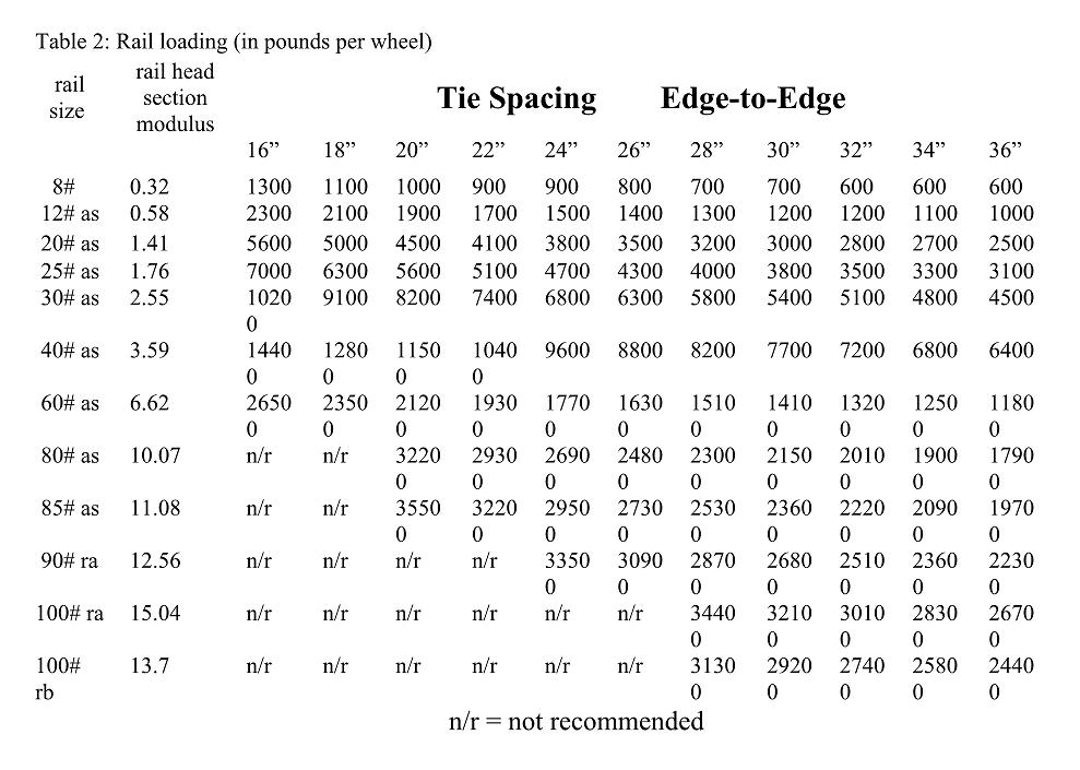
These equation and results are presented in Table 2.
table 2


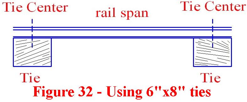
figure 1
The formula and the chart are based on point load supports (0.00" in width). In other words, the tie has a width of 0.00". If you use a 6" x 8" x 32" tie on 16" gauge track, then add 8" to the center to center tie spacing (Figure ??.2).
If you are using 20# rail and a loading of 3800# per wheel, you have a 24" free span (24" on center for point load supports), then the center to center tie spacing (center to center) would be 24". Add to that the tie width of 6" to get the center to center of 30".
Of course, a tie of 6" in width is not actually a point load so support loading conditions would change and negate the entire analysis for the support rail. However, the reason this works is that the 36 ksi steel (after having the safety factors applied) was calculated to be able to support only 16 ksi maximum. This is an overall safety factor of 1 - 16/36 = 56%.
This is back to the issue of acceptable tolerances or significant digits. The minute changes in loading configuration (along with items such as drilling holes for joining bars in the rail) are covered in the safety factor.
So if the point support has an actual width of 4", just add 4" to the center-to-center spacing in the chart.
Table 2 has several implicit assumptions and secondary results which I would like to bring out.
First, it assumes a single point load on the span between ties. If you have a tie spacing of 36” and your truck has a 24” axle spacing, these results are NOT valid. The easy way to avoid this problem is to use a tie spacing that does not exceed your shortest axle spacing.
Using a 24” tie spacing and 40# rail, the maximum wheel load is 9600 pounds. Assuming that you trucks axle spacing spacing is greater than or equal to 24”, you have an allowable axle loading of 19,200 pounds. For a 4-wheel car (like a bobber caboose), this is a total load of 38,400 pounds of car plus payload. If the car weighs 200 pounds, than the payload is 38,200 pounds.
If you are using a 4-wheel truck, then the truck is also allowed a 38,400 pound load. For a two truck car, this is 76,800 pounds or about 38 tons. If the car weighs in at a ton, then the maximum payload is 37 tons.
I have not seen the section modulus for 1” rail or 5/8” rail or 2” rail or any steel rail below 8#. However, the equations are good for any steel rail. If you wish to use aluminum rail, the section modulus and the allowable aluminum loading would be needed for the formulas.


