How did this work? I have some ideas, but...

If the throw lever was a simple pivot to give mechanical advantage to "bending the iron", then when in this position, the switch would be pushed to the other track. So, there must be some arrangement to make it move the same way as the lever is flipped.
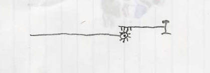
If the housing/pivot was like a rack and pinion gear, with the bottom of the lever attached to a shaft with a pinion gear, and the shaft to the rails had straight line rack-like teeth, with the shaft/teeth above the pinion gear, then the track would move the same direction as the lever and give more "leverage". My drawing is crude, but might get that idea across.

Any ideas? Mine would work, but it is the only thing I could think of that would fit in the dimensions of the photo of the throw.